NuukiaWorld project
Adding an answer/end call button to a headset
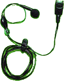
The original Nokia headset for the 5100/6100 series is equipped with a button on the microphone. The button may be used to answer an incoming call and to end a call. Unfortunately all headsets do not have such button. The target in this project is to install the button to a headset.
An answer/end call button is quite useful. When you previously kept the automatic answer function activated in the headset profile, you may have missed some calls. For example in noisy environment when your earphone has been dropped from the ear: Instead of a regular call, your "enemies" have been listened your secret conversations after the automatic answering. Also it is useful that you can control the answering manually, especially in situations where you are not ready to talk immediately.
It is quite impressing that the button is missing in so many headsets. It is very simple component in the headset circuit, in fact it is just only a button with no extra components. So it is easy to be installed afterwards, as described in the following paragraphs.
WARNING! Although the author has tested these circuits, no guarantee can be given for the operation or compatibility. If you do not understand the purpose of a single component in these circuits, do not build these devices. You are doing everything at your own risk.
Headset Interface
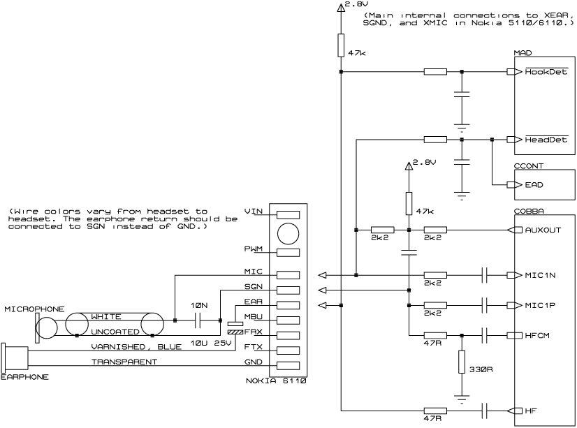
The main internal connections of the headset interface in Nokia 5100/6100 series phones are shown in the figure 1. The phone pulls XMIC input up with about 50 kilo-ohm resistance. (The AUXOUT pin is normally at high-impedance.)
Connecting the headset to phone causes the microphone itself pull down the XMIC pin (microphone has a low DC resistance). The processor ASIC "MAD" detects the low level at its HeadDet input and the phone switches to the headset profile.
During a call the baseband audio ASIC "COBBA" outputs a 1.5 V DC from its AUXOUT output pin. This biases the headset microphone into its working area. The AC signal generated by the microphone is received by COBBA with its headset microphone input MIC1. (With a car kit COBBA uses other inputs called MIC3 that does not contain a microphone preamplifier.)
COBBA outputs the sound with it accessory audio output HF. The HF output drives the headset earphone directly. However, the DC level of the XEAR pin is high because the low-resistance earphone must be separated with a capacitor from the phone. The phone pulls up the DC level of XEAR with 47 kilo-ohm resistance. Note that in the headset shown in figure 1, the earphone return is connected to the logic ground (GND, 9) of the phone, not to the audio signal ground (SGN, 4). According to Nokia's documentation it should be connected to the SGND. However, this difference does not affect the headset operation.
If the headset has the button switch, same button is used to answer and to end a call. Pressing the button causes the XEAR output of the phone to be connected directly to the earphone and the XEAR will be pulled down. MAD recognizes the low level with HookDet input.
There is also an additional connection from MAD's HeadDet pin to an AD converter in the power supply ASIC "CCONT". This is required because MAD's HeadDet input is unusable during a call; the XMIC voltage level is set by the COBBA AUXOUT. The MAD cannot detect disconnection of the headset during a call without CCONT's help.

Figure 1. The original circuit of the headset and the main connections to the headset pins in Nokia 5100/6100 series GSM phones.
Building Example
These paragraphs show an example of the headset button mounting. There may be differences in different types of headsets, so you may have to adapt these instructions to your particular case. The original circuit schematic of the third party headset used in this example is shown in left part of figure 1.
The button should connect the XEAR (EAR, 5) pin directly to the earphone by skipping the headset capacitor. However, the button should be installed near the earphone end of the headset, not near the capacitor in the connector case.
You can solve this problem by simple wiring changes in the headset: By switching the order of the capacitor and the earphone you can connect the button as shown in figure 2! You must remember to hold the correct polarity of the capacitor. I have also connected the earphone return now to the SGND instead of GND to follow Nokia's documentation.
Figure 2. The schematic diagram of the modified headset with the answer/end call button.
The physical mounting of the button is quite easy. Use a button with normally open contacts, and with about same pin spacing as the width of the cable.
The SGND signal is available on the shield of the microphone wire. The plastic insulation of the cable is taken away as little as possible to allow pulling very small wire loops out of the cable.
The varnish on the earphone wire is scratched away and the button is soldered directly on the wires. Finally the connections are covered, for example, with epoxy glue.
© Copyright 1999, 2000, 2002 Panu Tuominen. All rights reserved. Republishing this document partially or completely is forbidden. Internet hyperlinks to this page are allowed and such linking is encouraged. You are doing everything at your own risk. See the WARNING! in the top of this page.
For example, Nokia 5110 and Nokia 6110 are 5100/6100 series phones.


No comments:
Post a Comment